BVTKNodes Addon for Blender
Introduction
The Visualization Toolkit (VTK) is an open source library for scientific data processing and visualization. BVTKNodes is an addon for Blender (an open source 3D content creation and visualization tool). This addon makes it possible to create and execute VTK pipelines configured in Blender Node Editor, to produce objects like surface meshes, which can be then modified and visualized in Blender.
BVTKNodes provides Blender users with access to data readers for many scientific data formats, along with capability to convert VTK data into Blender objects. For VTK users, the add-on provides access to high quality photorealistic rendering and many kinds of mesh editing tools. The add-on was first presented at Blender Conference 2018. You can see more examples in a gallery thread on blenderartists.
Target Use and Users
BVTKNodes integrates VTK’s data processing capabilities with Blender’s powerful visualization features. It allows creation of photorealistic images and animations from scientific data.
Use of BVTKNodes requires both Blender and VTK skills. User needs to know at least Blender 3D Viewport, Node Editor, Materials, Lighting and Rendering basics, as well as VTK (to the extent required by users’ specific case). If photorealistic rendering or specialized VTK pipelines are not required, then it is suggested to use Paraview instead.
To learn Blender, see resources at blender.org , Blender 2.8 fundamentals series in Youtube and search for Blender tutorials on a topic. To learn VTK, see VTK wiki, the VTK Textbook and view VTK discourse forum. For BVTKNodes, see Help with Issues.
Technical Details and Limitations
BVTKNodes is based on automatic generation of Blender Node classes from VTK Python classes. Simply put, the addon makes VTK classes available as nodes in Blender. A manually programmed node class can supercede automatically generated code where needed. It is fairly easy to upgrade/downgrade to another VTK version, including customized VTK builds, so this makes BVTKNodes an option for prototyping and testing of VTK pipelines.
BVTKNodes includes many custom made nodes that make it possible to access VTK time step data, multi block data, and to color surfaces according to a customizable color ramp. For nodes which have not yet been fully customized for use in Blender, it is possible to add Custom Code for VTK objects. This is often needed, since many VTK objects require custom input from user to work correctly.
When update of the node tree is triggered, each parameter and value shown in the node is set to the VTK object represented by the node, unless the value is empty. It is not possible to affect the order in which values are set, which may result in unwanted behavior. In this case, please see Addition of Custom Code to VTK Nodes. Custom code is always run at last.
Warning
BVTKNodes is a bleeding edge software. Because both Blender and VTK are constantly evolving pieces of software, it is expected that customized parts in BVTKNodes can break when versions change. Many parts of the addon would benefit from further development. Addon is prone to crashing, and results should always be reviewed critically for bugs. There is no guarantee: you use the addon at your own risk.
Available Versions of BVTKNodes addon
1. simboden/bvtknodes
Original version of BVTKNodes for Blender version 2.79 using VTK 8.0.1. This version was demonstrated in the Blender Conference 2018 presentation.
2. tkeskita/bvtknodes
Upgraded and developed version for Blender 2.83 LTS series using VTK 9.0.1. Uses a new update system and a new mesh generator node VTK To Blender Mesh instead of the legacy VKT To Blender node.
Note
This documentation corresponds to tkeskita/bvtknodes version.
3. esowc/sci_vis
A version with new features for Blender 2.79b using VTK 8.2.0. Old Blender version is used for stability and animation features that are not yet working correctly in Blender 2.80 or newer.
Installation of VTK for Blender
BVTKNodes requires VTK to be available as a module in Blender’s Python environment. It is suggested to install VTK into Blender Python via Pip.
Note
Optional, for experts: Another VTK version (7 or later) may be alternatively used, but this requires compilation of VTK. Details are beyond this document, but to summarize briefly: If another version is used, then generated class definitions (gen_VTK*.py files) should also be updated (by running populate_db.py and generate.py. Warning: Modifications may be required). If you want to compile custom VTK, please see VTK building instructions for Linux.
Installation
- Install Blender (if needed, see instructions).
- Install VTK to Blender Python as instructed above in Installation of VTK for Blender.
- Download appropriate BVTKNodes add-on ZIP file (see options in Available Versions of BVTKNodes addon). To download add-on from Github, Select “Code”, then “Download ZIP”.
- Start Blender, go to “Edit” –> “Preferences” –> “Add-ons” –> “Install” –> open the add-on zip file.
- Activate the “BVTKNodes” add-on in Preferences by clicking on the checkbox. Add-on is located in Node category, “Community” level of Blender add-ons.
- For Blender 2.79: User Settings are located in File menu, and it is suggested to Save User Settings before closing settings.
Removal and Upgrading
Before installation of an updated version of BVTKNodes add-on, you should first remove the old version:
- Go to “Edit” –> “Preferences” –> “Add-ons” –> “BVTKNodes” -> Remove
- Close Blender and open again. Make sure BVTKNodes is not listed in the list of available add-ons.
- Follow Installation Instructions above.
Workspace Setup
BVTKNodes is used via BVTK Node Editor in Blender. These instructions help you set up a default workspace in Blender for BVTK (nodes), to make work easy.
Start a new file in Blender (File –> New –> General).
Delete default Cube object.
Duplicate the Layout Workspace (right-click –> Duplicate) and rename the new workspace (double-click on the name) to BVTK.
Split the 3D Viewport horizontally, and then vertically to create 3 window areas.
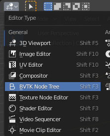
Change top area from top left corner into BVTK Node Tree. If you don’t have this option available, then there is something wrong in the installation.
In BVTK Node Editor, click New to add a new node tree.
Change one of the smaller areas into Text Editor.
In Text Editor, click on New and rename Text into BVTK.
Save this setup as a Blender file so that you can use it as a template when starting to process a new case.
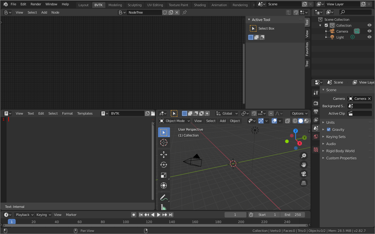
Example setup for BVTK workspace.
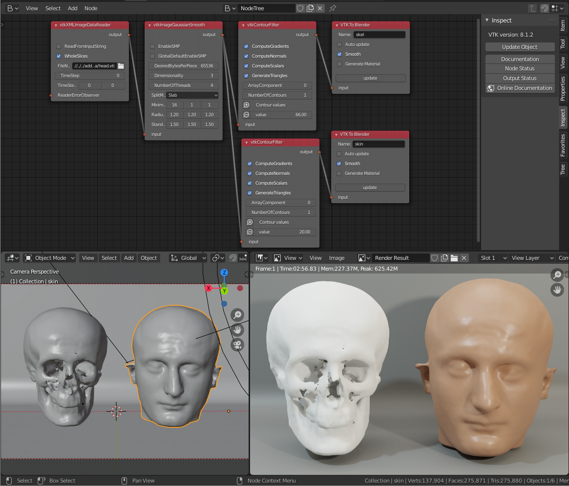
Simple Example: Human Head Visualization
Here are the steps to create the meshes for the example shown in Introduction. For other examples, see Tree tab below.
- The data file head.vti is located in examples_data folder in the sources. You can also download head.vti from github.
- Create node setup as shown in the image in Introduction. You can add nodes from Add menu or by shortcut key shift + A. Link nodes by dragging from a connector to another connector.
- Set FileName in vtkXMLImageDataReader node by clicking on the folder icon and select head.vti file.
- In vtkContourFilter node click plus icon to add a contour value, then set the value.
- In VTK To Blender Mesh node, add name to mesh object, set Generate Material on, and run Update. A mesh object should now appear in the 3D viewport. Repeat this for the other VTK To Blender Mesh Node.
- At this point, BVTKNodes should have created two (overlapping) mesh objects, which are shown in the Blender Properties Editor.
- Save Blender file.
In practice this is the end of the BVTKNodes part. The rest of the visualization includes steps in Blender: moving of objects, creation of background plane object for visualization, setting up camera, setting up lighting and world backround, modification of materials for objects, modify settings for rendering engine, rendering of image, possibly composition and finally saving of image file. To learn about those, it is suggested to search for Blender tutorials on-line.
Node Status
The tkeskita/bvtknodes version of BVTKNodes includes a modified core update system for nodes, which fully separates node editing in Blender from updates on the VTK Object level, to allow control over updates. Each BVTK Node has a Node Status, which is indicated by the color of the node background, to show the current status. Main node statuses include
- Out-of-date (green) - Node and VTK level are not in sync. VTK Object might not yet even exist.
- Updating (blue) - VTK level is currently being updated to match current node properties.
- Up-to-date (dark gray)- Node and VTK level are in sync. VTK Object exists in memory.
- Upstream-changed (orange) - Some value in an upstream node has been changed. Node and VTK level may not be in sync, and update is needed.
- Error (red) - Setting a value from node to VTK Object, or running of a VTK command, has failed. Execution has been stopped.
Using these statuses, it is possible to build different VTK level updating systems, without binding node editing operations with updates (see Update Mode in Inspect Panel).
Tabs in BVTK Node Editor
Tabs are located in the Sidebar of the BVTK Node Editor. You can hide and view the Sidebar by pressing “N” key while hovering mouse over the BVTK Node Editor. Note: Some tabs become visible only after you select a VTK node in the node tree. The properties and operations shown in tabs will affect the active node.
Item, Tool and View Tabs
These tabs are just default Blender tabs, which show node properties, node tools and view.
Properties
- Show/Hide Properties shows list of VTK object boolean properties, which can be hidden or shown in the node based on this setting. Values for hidden properties are ignored (not set to VTK objects during updates).
- Edit Custom Code operator copies node’s custom code into BVTK Text Block in Text Editor, where it is possible to add and edit Python code. The code will be run, line by line, for the VTK object represented by this node when the node is updated.
- Save Custom Code operator saves the text from the BVTK Text Block into custom code storage string of the active node. Custom Code will be shown in the node (editor screen updates when mouse cursor enters it) if there is any saved to it.
Inspect
This tab contains global settings, tools for debugging and information.
- Inspect tab shows the VTK version at the top.
- Update Mode is a global setting which determines when changes
made in node properties are updated to the corresponding VTK Object
and output.
- No Automatic Updates will trigger no updates. Downstream nodes are only informed that a change was made (status changes to Upstream changed).
- Update Current Automatically will only update current node and upstream nodes, if they are out-of-date.
- Update All Automatically will update upstream nodes (if needed), the current node and downstream nodes automatically.
- Update Node operator will call a node specific update routine on the active node. The update routine initializes a VTK object (if no VTK Object exists), sets properties from node to the VTK Object and runs VTK level update command(s). This operator is available also on nodes, but only if the node status is not Up-to-date.
- Documentation will show doc string of the VTK object in the BVTK Text Block in the Text Editor.
- Node Status will show status of the VTK object in the BVTK Text Block in the Text Editor.
- Output Status will show status of the VTK object in the BVTK Text Block in the Text Editor.
- Online Documentation will open up web browser showing the Doxygen generated documentation for the very latest nightly version of VTK. Warning: Documentation may not exactly match the version of VTK used in BVTKNodes!
Favorites
This tab lists favorite nodes. You can delete and add nodes for easy access here.
Tree
Node tree related operations.
- Export JSON exports the current node tree as JSON file.
- Import JSON imports the current node tree as JSON file.
- Arrange will try to arrange node tree for a clean view. Warning: Does not work well for complex node trees.
- Examples contains a selection of example node trees you can try out.
VTK Nodes
All node names that start with lower case text ‘vtk’ using camel case naming convention represent the VTK classes directly, for example vtkArrowSource. All other nodes are special nodes for BVTKNodes.
Some VTK classes include several overlapping methods to specify values, e.g. vtkConeSource has options for Angle, Height and Radius, two of which is enough to specify (third property can be hidden in Properties tab to disable it). If all are specified, then the latter values take precedence. You can hide unwanted properties (see Properties tab). Hidden properties are ignored during updates.
Note
Some VTK operations require use of vtkPassArrays, vtkAssignAttribute or a node specific function to activate arrays to operate on to get correct result, even if there is only one array in input. See examples in Node Examples for Unstructured Grids.
Addition of Custom Code to VTK Nodes
Many VTK nodes require special input from the user, depending on the node, to work correctly. For any VTK node, it is possible to add a Custom Code block for special input commands. Each line of code must be a command that can be run directly for the VTK object (e.g. set a value or call an object method). You can select a VTK node, and then use Online Documentation operator in Inspect Tab to find out about VTK specific commands and values. Lines starting with # are ignored as comment lines. Custom Code is run after the settings shown on the node have been set to the VTK object, so it is possible to overwrite settings with Custom Code.
Editing of Custom Code is done using Blender Text Editor:
- Select a VTK node in BVTK Node Tree
- In Properties Tab, run Edit Custom Code.
- Go to Blender Text Editor, and add/edit code in BVTK text block.
- To save edited text to active node, run Save Custom Code in Properties Tab. Updated code is shown on the node bottom when mouse cursor enters BVTK Node Tree area (see bottom example in Extract Boundary Surfaces, vtkOpenFoamReader node)
You can find Edit and Save buttons also directly on the node if the node is up-to-date: Click on the eye icon on the node bottom right part to see the custom code and the operator buttons.
Customized VTK Nodes
Various VTK nodes have been customized to ease use in Blender (see Customization of Node Python Code):
vtkPlane
This node specifies an infinite plane suitable for e.g. slicing 3D VTK cell data (see example Cutting Field Data). Plane can be specified by manual input of Normal and Origin vectors, or by selecting an existing Blender Object (must be either a Plane or an Empty Blender Object type) from the Orientation Object dropdown menu. The location and rotation of the named Blender Object is used to calculate Normal and Origin for vtkPlane.
Special Nodes
VTK To Blender
This is the original main node, which converts VTK surface mesh data into a Blender mesh. This node has been superceded by the VTK To Blender Mesh node in the tkeskita/bvtknodes version.
VTK To Blender creates faces directly out of VTK cell vertex lists, without any pre-processing. This works well when VTK data consists of simple cells with ordered vertices as input, such as e.g. trigonal or quadrigonal boundary faces generated with vtkGeometryFilter. Direct conversion of 3D cells or polygons does not work correctly.
- Name specifies the object and mesh names for the Blender object which will be created. Note: Any pre-existing mesh will be deleted upon update.
- Auto update: If enabled, the node tree will be updated immediately whenever a value in a node is changed. If not enabled, the user must run Update operator manually to update Blender object and mesh after changes.
- Smooth will set surface normal smoothing on for the mesh if enabled. Note: You may need to visit Edit Mode for the object in order to show correct shading in the 3D Viewport after running Update with Smooth option enabled.
- Generate Material will generate an white diffuse default material and assign it to this object. Warning: Any existing material is overwritten if enabled.
- Update executes the node pipeline connected to this node.
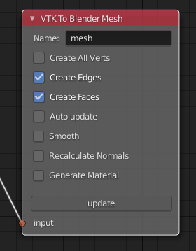
VTK To Blender Mesh
This is the new main node for exporting vertices, edges and boundary faces directly from VTK objects into a Blender mesh object, without need for any additional pre-processing nodes. Conversion is carried out for all linear VTK cell types as well as polyhedrons. The node contains same basic options as VTK To Blender node with following additions:
- Recalculate Normals: This option will automatically compute and set “outward” normals for faces, regardless of original face normal directions.
- Create All Verts: If disabled, only boundary vertices (vertices part of boundary faces and edges) are created. If enabled, all vertices (including internal and unconnected vertices) are exported.
- Create Edges: If enabled, exports also wires (edges that are not part of any face).
- Create Faces: If enabled, creates boundary faces (faces used by only one VTK cell). Internal faces (faces shared by two 3D cells) are not exported.
VTK To Blender Particles
Warning
This node is experimental! There is an issue with rendering where render does not show particles and rendering hangs.
This node converts VTK point data (points of vtkPolyData) into a Blender Particle System. It allows use of Blender particle object instancing, which allows glyphing of point data (presentation of points with a mesh object). Since object instancing uses little memory, a large number of points can be visualized efficiently.
- Name is the name of the particle object to be created.
- Glyph Name is the name of the glyph object which is to be instanced at point locations. For oriented glyphs, the glyph should be 1 m in length, and point towards positive X axis. Note: Node will not work correclty unless a glyph object is specified.
- Direction Vector Array Name (optional): Name of a VTK vector data array, with which the glyph object will be aligned at point locations.
- Scale Value or Name (optional): A constant multiplier value or name of a VTK scalar array used to scale the glyph object at point locations.
- Color Value Array Name (optional): Name of a VTK scalar array of ramp values that will be used for coloring the object at point locations. Color ramp values are available via Particle Info node’s lifetime output (until a better access becomes possible).
- Particle Count specifies the maximum number of particles which will be converted into the Particle System.
- Generate Material will generate a default colored diffuse material which will be used for glyph object at particle locations.
- Initialize operator will initialize the Blender Particle System with the number of particles specified in Particle Count. This operator must be run before node pipeline is updated.
- Update executes the node pipeline connected to this node.
Usage: First, create a glyph object. Then input the data in node fields, and run Initialize. After that, every change of frame number in Blender Timeline updates the particle data. Note:
- Change of frame number in Blender Timeline is required to update particle data correctly.
- Particles may not show up updated in the 3D Viewport after frame change, but they should be still rendered correctly.
- Particle colors show up correctly only in Rendered Viewport Shading mode, and only using Cycles Render Engine.
- It is not possible to modify particles in Blender. You need to do all modifications on VTK side prior to using this node.
VTK To Blender Volume
This node is currently obsoleted, since it requires custom build of Blender dependency libraries to enable pyopenvdb in Blender, in order to convert 3D VTK image data (vtkImageData) into OpenVDB grids. Instead, please use the VTK To OpenVDB Exporter node described next. If pyopenvdb becomes a standard part of Blender one day, this node can be resurrected.
VTK To OpenVDB Exporter
This node exports selected 3D vtkImageData arrays (density, color, flame and temperature inputs) into a JSON file, which can be then converted into OpenVDB (.vdb) file format using an external installation of pyopenvdb. OpenVDB files can be then imported back to Blender as a Volume Object for volumetric rendering, using e.g. the Principled Volume Shader.
- Name is the base name of the OpenVDB file to be created.
- Density Field Name specifies the field name of scalar array to be used for the Density output of Volume Info node in Blender Shader Editor.
- Color Field Name is used for 3D vector array as Color output in Volume Info node.
- Flame Field Name is scalar field exposed as Flame output in Volume Info node. It can be used for specifying e.g. emission strength.
- Temperature Field Name is a scalar field shown as Temperature output in Volume Info node.
Upon running Update Node, the node creates a file like
volume_00001.json (format is name + frame number) into the folder
where the blender file is saved. If node input is not a data suitable
for exporting (VTK 3D Image Data or Structured Points Data), the node
shows an error message, otherwise data dimensions are shown.
To convert JSON file to OpenVDB, the user must run a Python script
convert_to_vdb.py located in the add-on source directory
utils. You can also download script directly from github.
Example usage of command:
python3 convert_to_vdb.py volume_00001.json
Note
- If you receive error like:
- “libjemalloc.so.2: cannot allocate memory in static TLS block”
- then prepend command with LD_PRELOAD with correct path to libjemalloc.so.2, e.g.:
LD_PRELOAD=/usr/lib/x86_64-linux-gnu/libjemalloc.so.2 python3 convert_to_vdb.py volume_00001.json
Running convert_to_vdb.py requires that pyopenvdb module is available to Python. pyopenvdb can be provided externally, depending on your system:
- Ubuntu Linux : install system package:
sudo apt-get install python3-openvdb - Windows: ???
If you find out free packages that provide pyopenvdb, please comment here.
See also other alternative routes from VTK to OpenVDB.
Hint: Add Math or Vector Math nodes in the Shader Editor to modify array values to obtain wanted visual results, instead of adding the mathematical manipulation of the arrays in BVTKNodes. See OpenVDB Export and Volumetric Rendering example.
VTKImageData Object Source
This node creates an empty 3D VTK image data (vtkImageData) object.
- Origin is the origin coordinates of the image data.
- Dimensions set the number of voxels in each primary axis.
- Spacing specify voxel side lengths in the three axes.
- Multiplier scales both all Dimensions and all Spacing values while (approximately) retaining image bounding box size.
Info
Info node shows information about the VTK pipeline, and is useful for VTK debugging purposes. It is best to try to use this node whenever uncertain of what the current VTK pipeline contains. Currently it shows:
- Type of VTK data.
- Number of points and cells in VTK data. Note: “cell” in VTK terminology can refer to a face or a 3D cell.
- X, Y and Z coordinate ranges of the data.
- Point and cell data (with names, type and value ranges) included in the pipeline.
Color Mapper
This node assigns color to mesh data. You will see the colors in Blender 3D Viewport when Shading Mode is set to either Material Preview or Rendered.
- input connector is connected to an input node.
- lookuptable connector must be connected to a Color Ramp node, which specifies the colors for the value range.
- Generate Scalar Bar will generate a color legend object to the Blender scene. Warning: This feature is not working currently well. Alternative for this is to prepare a separate color legend image in an image manipulation program and composite that on top of the result images.
- Color By is a text field which specifies the data array for which coloring is carried out. The first character determines the array type (“C” for cell/face values, or “P” for point values), and the characters starting from third position specify the array name. Second character is not used. For example, “P_pressure” specifies coloring by point data in “pressure” array. If preceding nodes are up-to-date, the dropdown menu on the right will provide a list for selection.
- Auto Range will update the value range for the data array specified in Color By automatically during update, if enabled.
- min and max specify the value range (if Auto Range is disabled).
- output connector should be attached to a VTK To Blender Mesh node.
Multi Block Leaf
This node allows you to filter to a single data set, when the input is of type vtkMultiBlockDataSet. This is often required prior to processing of a specific array data when a VTK Reader provides multi block data. Block Name text field specifies the data set name. If preceding nodes are up-to-date, the dropdown menu on the right will provide a list for selection.
Time Selector
This node can be connected immediately after a VTK reader node to control which time point of transient (time dependent) data is to be processed.
- If Use Scene Time is enabled, time is directly controlled via the Blender Timeline Editor. If the frame in the Blender Timeline Editor is changed, then Time Index in the Time Selector node is automatically updated to correspond that frame number.
- If Use Scene Time time is disabled, then it is possible to use Global Time Keeper node to animate the Time Index value (see below).
- If the VTK Reader is not aware of time data, and if File Name of the Reader node contains integers at the end of the File Name, then the integer part of the File Name is updated to correspond to Timeline frame number. This allows animation of time series data for readers that are not aware of time (e.g. vtkPolyDataReader, which can read point and surface data from .vtk files).
Global Time Keeper
The Global Time Keeper node is a special node that allows animation of values in BVTK Nodes using the Blender animation system using keyframes. This is done by reimplementing the keyframe functionality, which is not available in custom node trees currently. Keyframe handling in BVTK is similar to the rest of Blender, i.e. keyframes can be inserted on properties by pressing I on your keyboard when hovering over a property that is animatable. Alternatively, you can right-click and use Insert Keyframe, or Clear Keyframes to edit the keyframes. For more information, please read the official Blender documentation on keyframes.
In order for BVTKNodes to actually update the values of the keyframed properties, the Global Time Keeper node must be inserted into the node tree. Running Update Node after a frame change will update all keyframed property values. The node also shows all properties in the node tree that currently have keyframes along with the keyframe values.
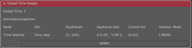
Note
Since this implementation is an unofficial reimplementation of the animation feature, it does not support all features:
- The keyframes are not accessible over the Dope Sheet or Graph Editor
- Interpolation mode is always set to linear for all properties
Python Interaction and Custom Filter
It is possible to interact with nodes and live VTK objects via Blender’s Python Console. Python Console includes three help operators for BVTKNodes:
- Get Node operator inserts text which returns access to active node.
- Get VTK Object inserts command which returns access to VTK object of the active node.
- Get Node Output inserts text which returns the Output of VTK object.
Additionally, there is a Custom Filter node available, which allows user to write all of the Python code in a Blender Text Block, which is run at node location. For example, this code returns first block from the input, similar to Multi Block Leaf node:
def get_first_block(input):
  return input.GetProducer().GetOutput(0).GetBlock(0)
Here is another example of a Custom Filter which calls vtkThreshold with custom parameter values:
def myThreshold(input):
  vtkobj = vtk.vtkThreshold()
  vtkobj.SetInputData(input)
  attr_name = "p" # Array name for thresholding
  attr_type = vtk.vtkDataObject.FIELD_ASSOCIATION_CELLS
  value1 = float("0.01") # min value
  value2 = float("0.02") # max value
  vtkobj.ThresholdBetween(value1, value2)
  vtkobj.SetInputArrayToProcess(0, 0, 0, attr_type, attr_name)
  vtkobj.Update()
  return vtkobj.GetOutput()
Note: Writing code for Custom Filter requires knowledge of VTK. Please refer to VTK documentation for class specific information.
Customization of Node Python Code
If an automatically generated node does not provide good functionality, it is possible to override the autogenerated node code with custom Python code. An example of such a node is vtkThreshold, used for getting points or cells for which a field value is between a lower and an upper threshold value. The automatically generated code (see class VTKThreshold in source file gen_VTKFilters1.py) does not support specification of array name, ranges and data type for thresholding. It is always possible to provide these as Custom Code, but to make the node easier to use, the code for class VTKThreshold was copied to file VTKFilters.py, modified and commented, and add_class and TYPENAMES.append commands needed for registering were added. Please feel free to submit such node code customizations at github issues page!
Information and Error Messages
Nodes show messages at the UI message box at node top, if any text is available. These messages are used to show information and also errors for the user. In addition, node is shown in red color if an error is encountered. Unfortunately, VTK level error messages are not currently captured to this message, so you may need to see debugging messages (see below) when trying to find out cause for a failure.
Debug Messages
Please use Info node for viewing pipeline contents.
BVTKNodes additionally uses Python Logging module, which prints out
debug messages to the terminal where Blender is started, but only when
Python Logging is configured properly (see Configuring Logging chapter
in Logging from Python code in Blender).
These messages may be helpful for debugging purposes. In the simplest
case on Linux, you can create a text file
$HOME/.config/blender/{version}/scripts/startup/setup_logging.py
with contents
import logging
logging.basicConfig(format='%(funcName)s: %(message)s', level=logging.DEBUG)
Please check the Development section for more information for developers.
Other Resources
There are some examples in Blenderartists BVTKNodes gallery discussion thread.
Help with Issues
You are free to ask and give advice for specific use cases at github issues page. Please check this list first though:
Read through these docs first, and view examples in Node Examples for Unstructured Grids.
Run Force Update on the final VTK To Blender Mesh node to update the preceding nodes.
For time dependent data, try to change frame number in Blender Timeline Editor.
Check the list of both open and closed issues, in case your problem has been mentioned already.
Check that you use a supported VTK version, see Available Versions of BVTKNodes addon. You can see VTK version in Blender Python Console (by default located in the Scripting workspace ) with commands
import vtk
vtk.vtkVersion().GetVTKVersion()
Please provide an image of your node setup with a resolution high enough to read the node contents.
Please include output of an Info node in an image, so it is clear what data your pipeline contains. Info node can be attached after a Time Selector node, a Multi Block Leaf node (if you use one), or directly after a data reader node.
If possible, please provide a small example data file.